UMS Mega Keys – DIY

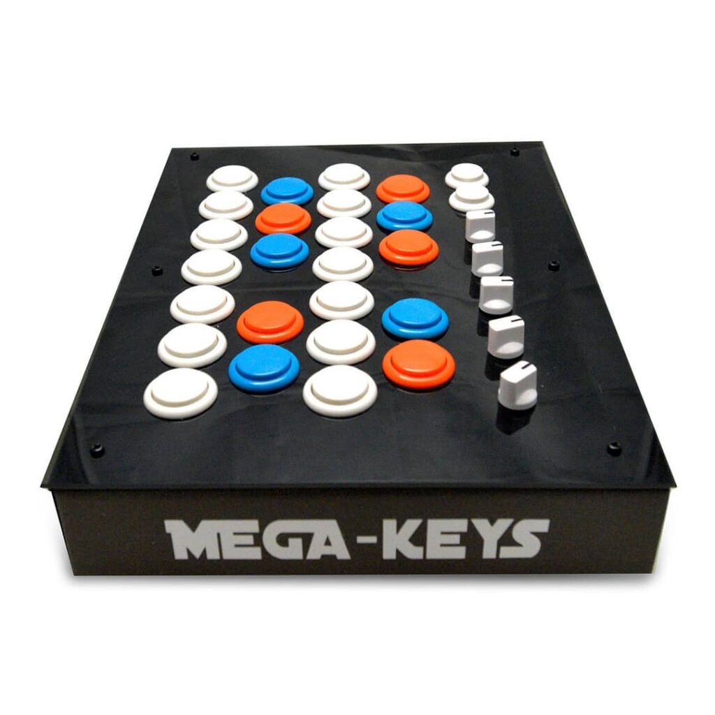
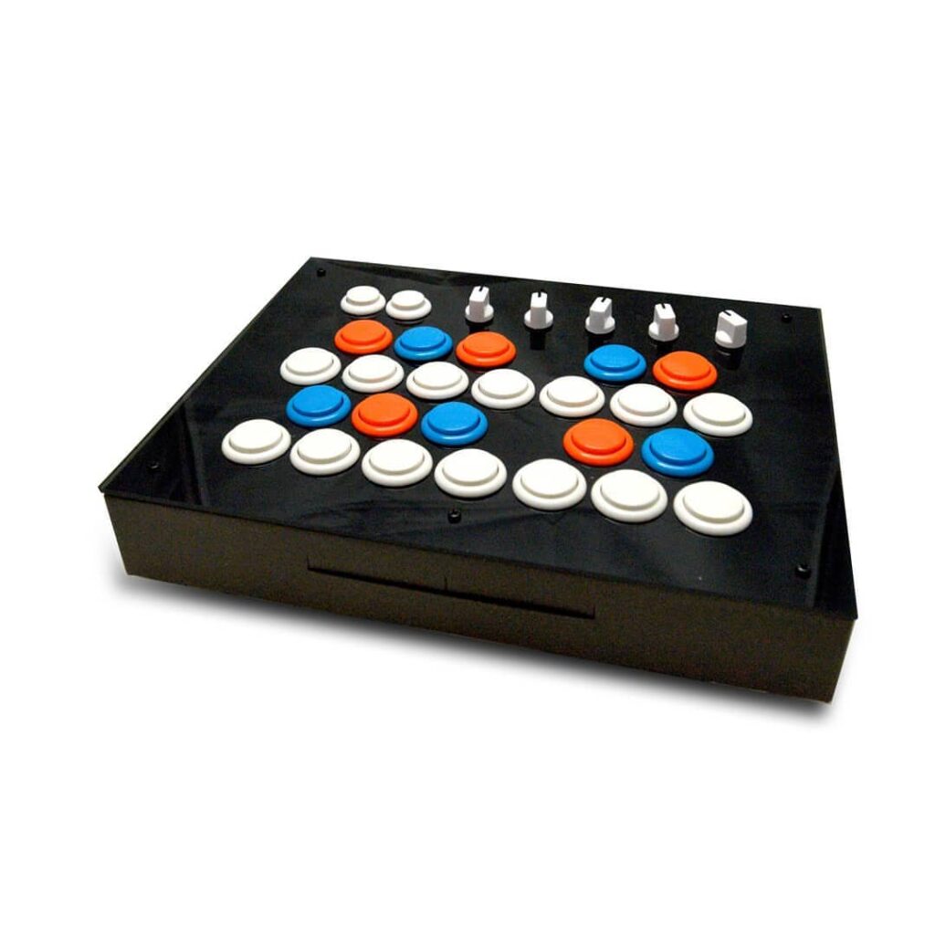
UMS Mega Keys is a perfect MIDI-Class-Compliant controller tailored for producers, programmers, musicians and DJs. Powered by Arduino Mega R3 microcontroller and available as DIY Kit with snap-on parts, Mega Keys allows user full learning experience on how to build a MIDI Controller with step-by-step instructions on its assembly.
Features
- 26 retro arcade game butttons with color options
- 5 assignable potentiometers accessible via 4 banks
- USB-powered; no power adapter required
Specifications
- Arduino Mega R3
- Dimension: 32cm x 25cm x 5cm
- 5V USB-powered.
Parts
- Arduino Mega R3 x 1
- Mega Control Breakout Board x 1
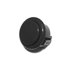
- Push Button – 30mm x 24
- Push Button – 24mm x 2
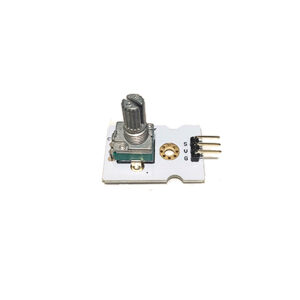
- Rotary Sensor x 5
- Push Button Wires x 4 Sets
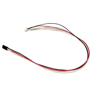
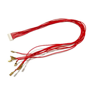
- Potentiometer Wires x 5
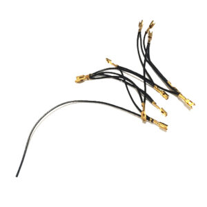
- Ground Wires – Daisy-chained x 4
- Enclosure x 1
-
Product on sale
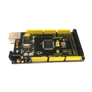 Adruino Mega R3 – Key-E-Studio (Preowned)Original price was: $50.00.$45.00Current price is: $45.00.
 -
Product on sale
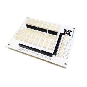 Mega Control Breakout BoardOriginal price was: $30.00.$25.00Current price is: $25.00.
 -
 Push Button – 24MM (4-Pack)$10.00
 -
 Push Button – 30MM (4-Pack)$12.00
 -
Product on sale
 Rotary PotentiometerOriginal price was: $7.00.$5.50Current price is: $5.50.
-
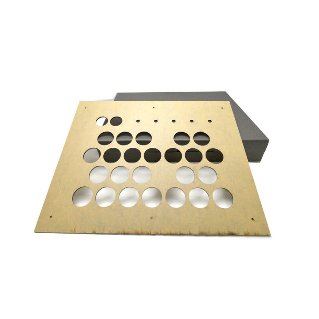
 Faceplate – Mega Keys$20.00
 -
 Potentiometer Wires – (5-pack)$15.50
 -
 Ground Wires – Daisy-Chained (5-pack)$22.50
 -
 Mega Control Push Button Wires – (3-pack)$22.50
 -
Product on sale
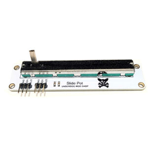 UMS Slide PotentiometerOriginal price was: $10.00.$8.50Current price is: $8.50.
-
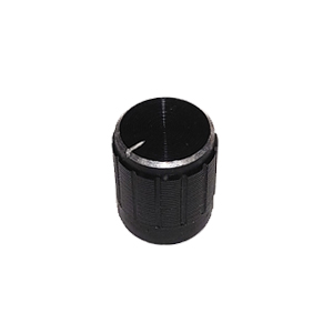 Black Metal Cap (4-Pack)$12.00
Assembly Steps
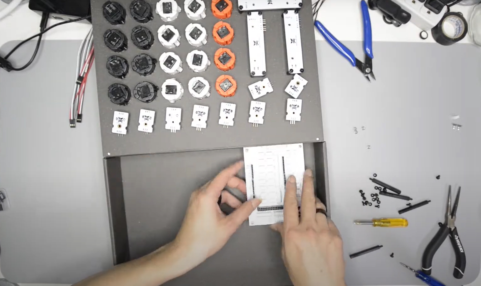
Preparing the Parts
Parts
Click on “Parts” tab to see a list of parts required to build this controller.
Get the Firmware – Making It A MIDI Compliant Device
Install the Mega Control driver for the ATmega16U2:
Click here for detailed steps on flashing firmware to make Arduino board into a MIDI Compliant Device.
Uploading Codes Into Arduino Mega
Install Arduino IDE
Click here for detailed steps on downloading and installing Arduino IDE.
Click here for detailed steps on uploading code into an Arduino board.
Assembling
Simply follow the steps below to build your controller.
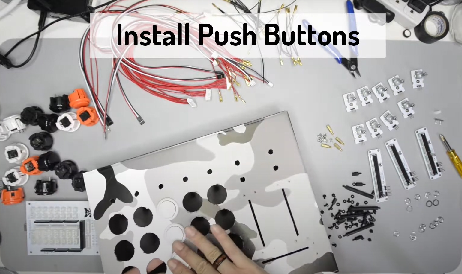
Install Push Buttons
Snap the buttons into the holes on the faceplate. Ensure a snug fit. Each button should click into place. Try and mount them so the legs are vertical relative to the enclosure.
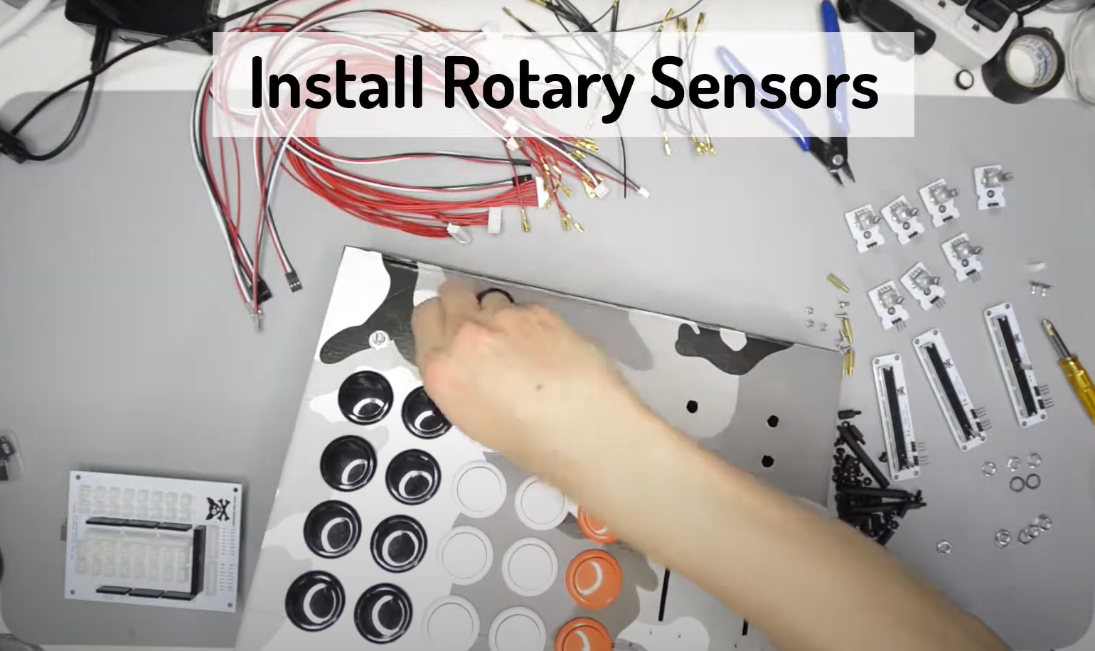
Install Rotary Sensors
Potentiometer knobs will then be placed in with washers and nuts, tighten with pliers. Insert the potentiometer through their corresponding holes from the underside of the faceplate. Ensure the nut is very tight so that it does not loosen while using the potentiometers.
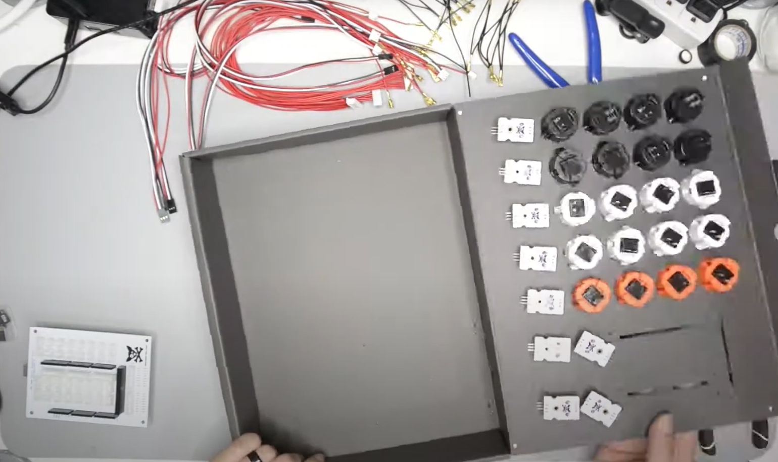
Screwing In Rotary Sensors
Ensure that each potentiometer is facing the same direction when screwing them in. This will make wiring a bit easier in the next step.
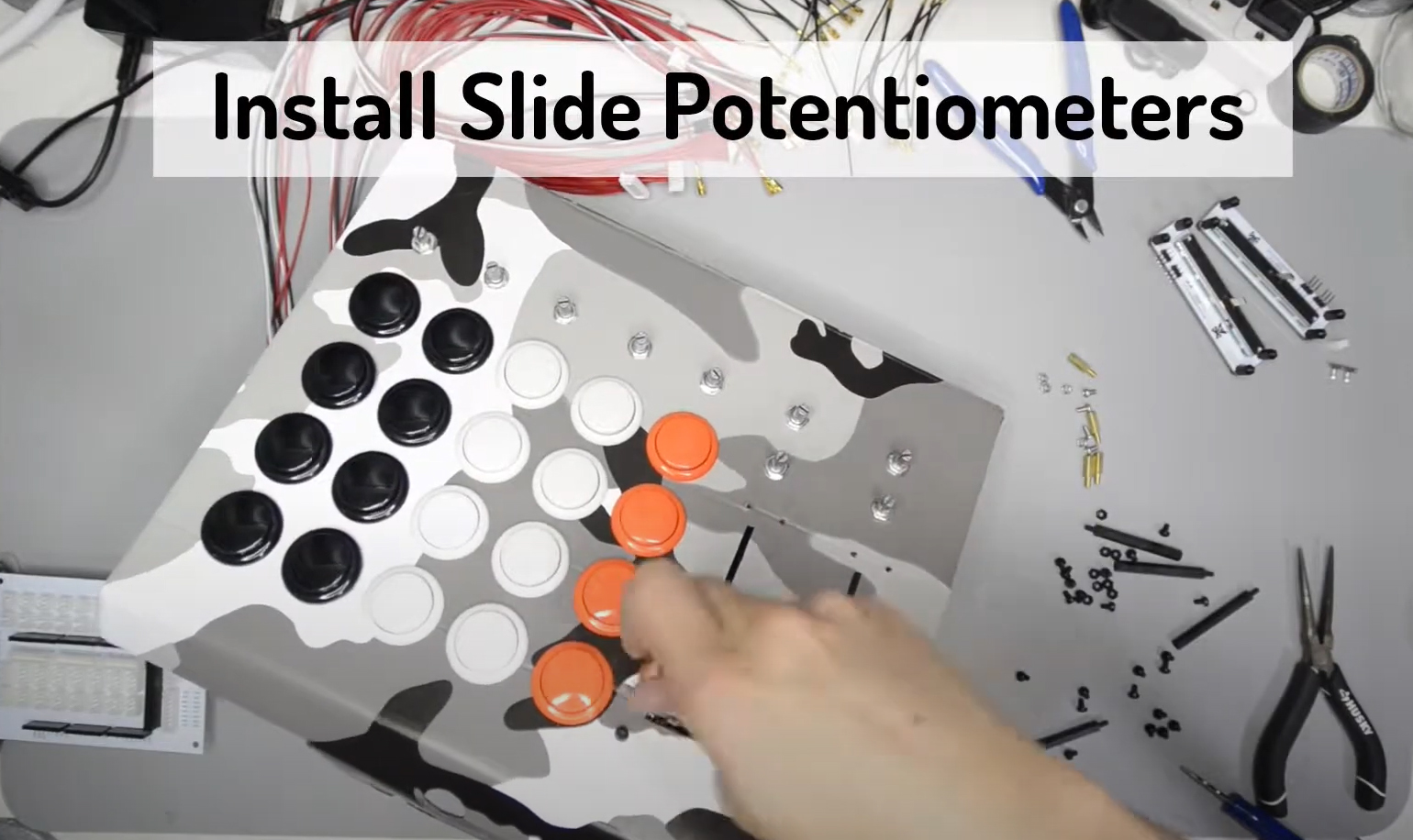
Install Slide Potentiometers
Mount the M3 hex standoffs to each corner of the UMS slide potentiometer, secure them with M3 nuts. One by one, secure slide potentiometer onto the faceplate using M3 screws. Tighten just enough for a snug fit, but not enough to bend or break the potentiometer.
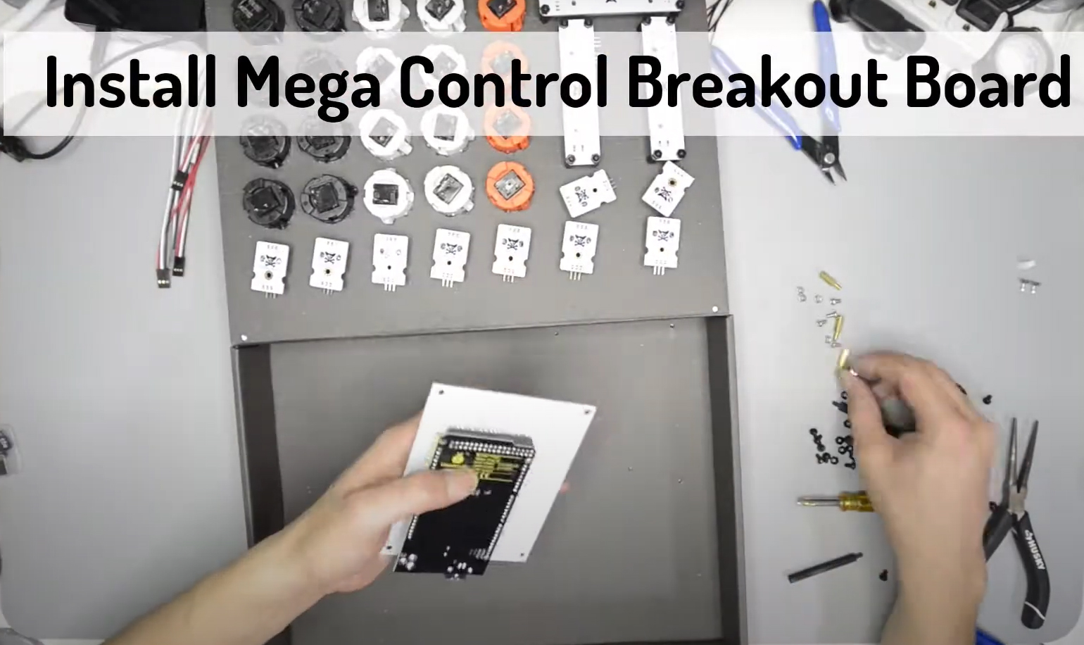
Install Mega Control Breakout Board
Place Mega Control Breakout Board on top of the Arduino Mega R3. The pins on the breakout board should match perfectly to Arduino Mega board. Fix the hex stand-offs to the four corners of the breakout board using M3 screws.
Secure Mega Control Breakout Board to the Enclosure
Insert the Arduino Mega + Breakout Board into the enclosure. Secure the board to the enclosure with M3 nuts from bottom of the enclosure.
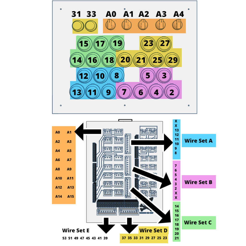
Wiring
Click on “Wiring” tab to see the wiring diagram. Connect each Push Button and Potentiometer with its corresponding number to the Arduino Mega Pinout.
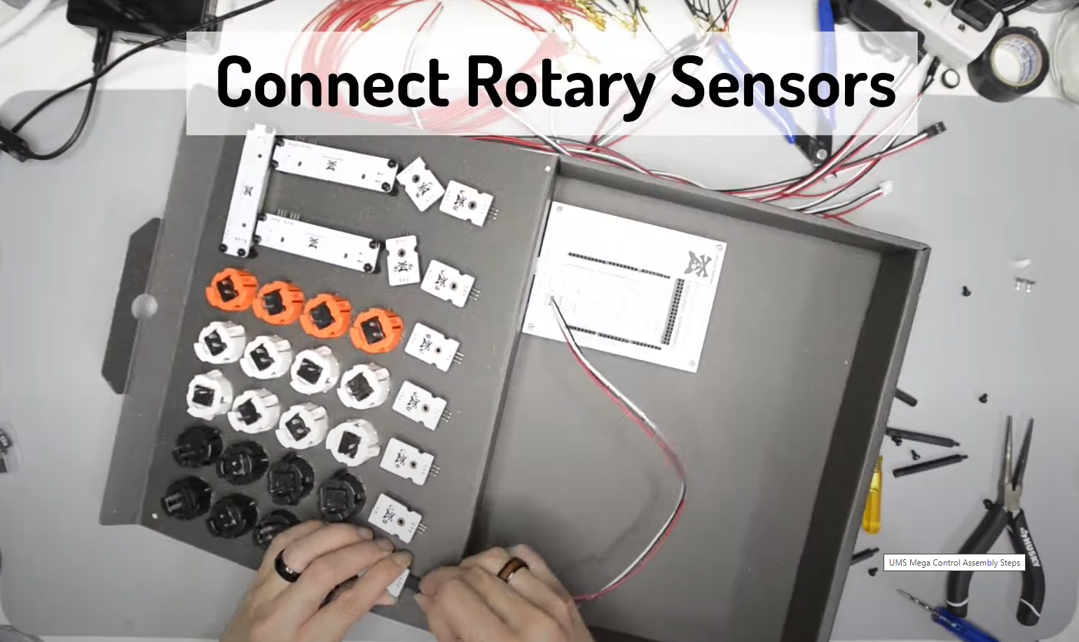
Connect Rotary Sensors
Easily connect Rotary Sensors to the Breakout Board using custom UMS Potentiometer Wires. Alternately, we can also using regular color coded wires. Connect using long red wires from the positive leg, black wires to the ground, and white wires for 5v power.
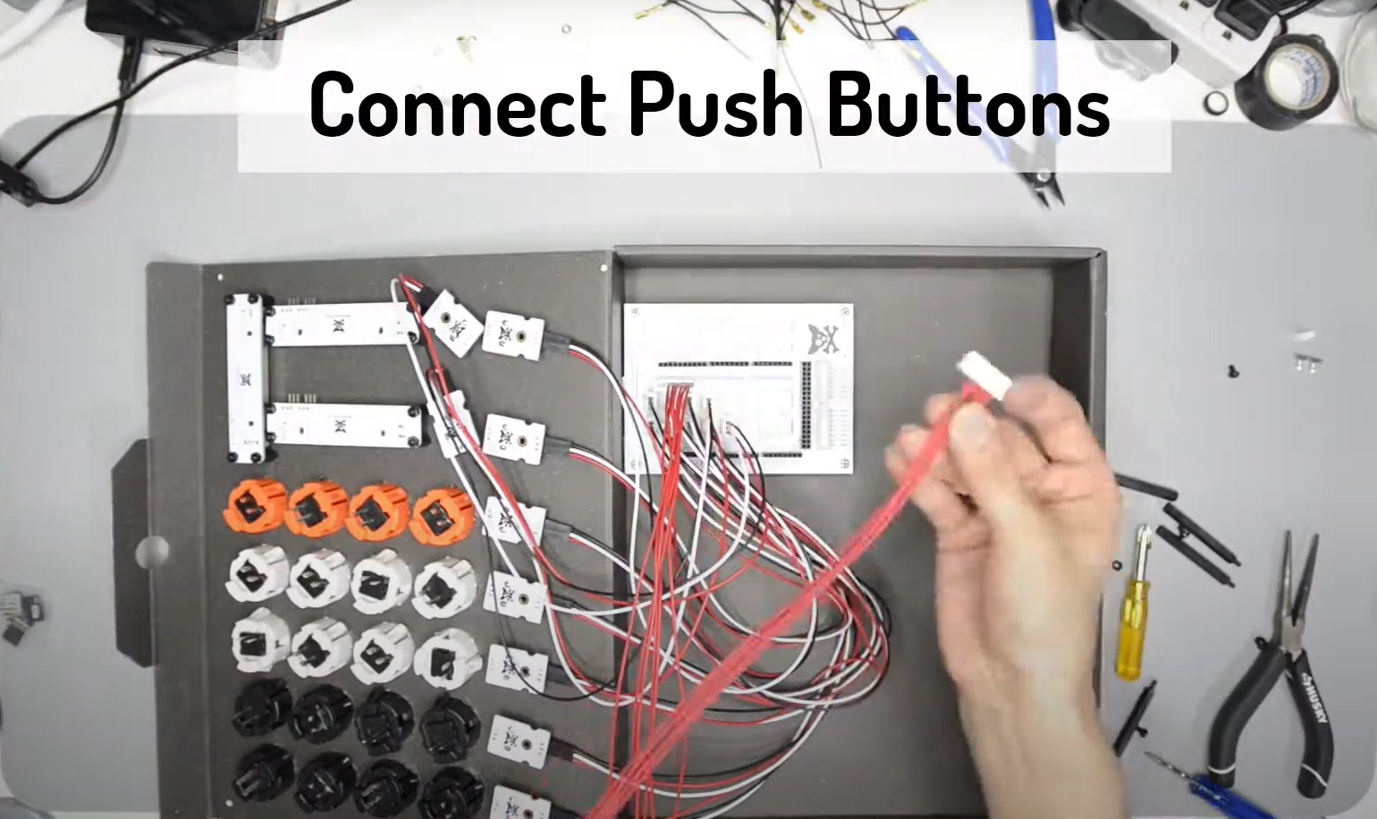
Connect Push Buttons
Connect long red wires from the positive leg of an arcade push button directly to the Mega Control Breakout Board. Follow the wiring diagram to connect each button to its respective pins on the Breakout Board.
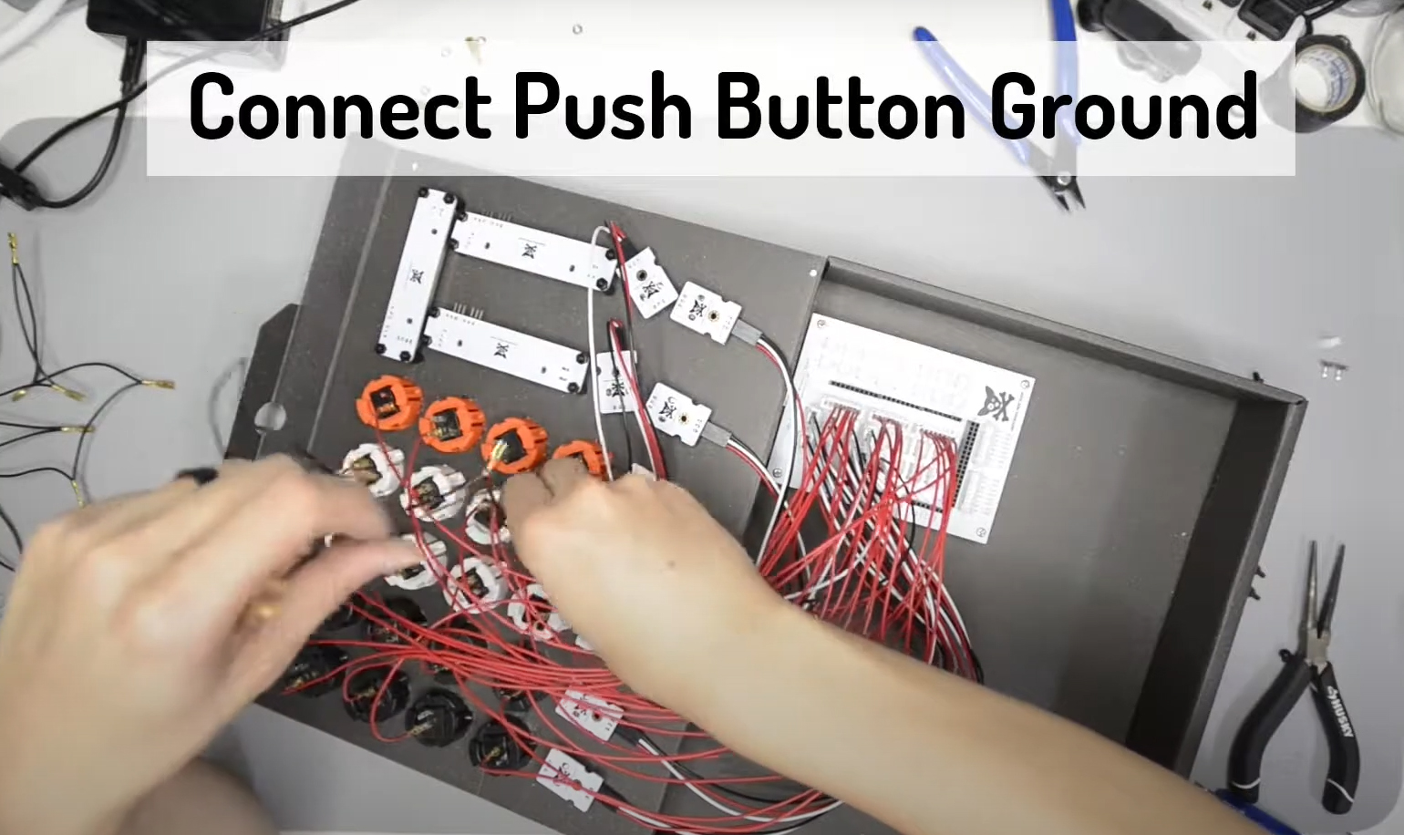
Connect Push Button Ground
Connect black wires joining all the negative leg of the arcade push buttons. We have daisy-chained ground wires available to make this task slightly easier.
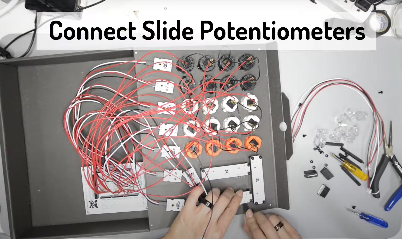
Connect Slide Potentiometers
Connect Slide Potentiometers to the Breakout Board using custom UMS Potentiometer Wires the same way as connecting Rotary Sensors.
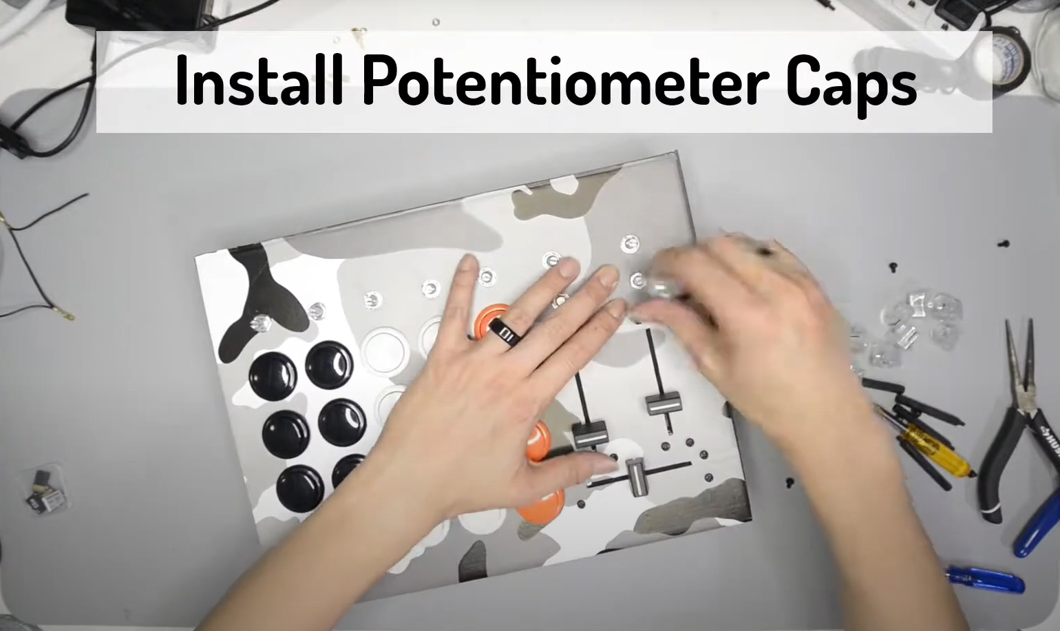
Install Potentiometers Caps
Spin each potentiometer as far counter-clockwise as possible, place the provided cap so that the notch points toward the 7 o’clock position.
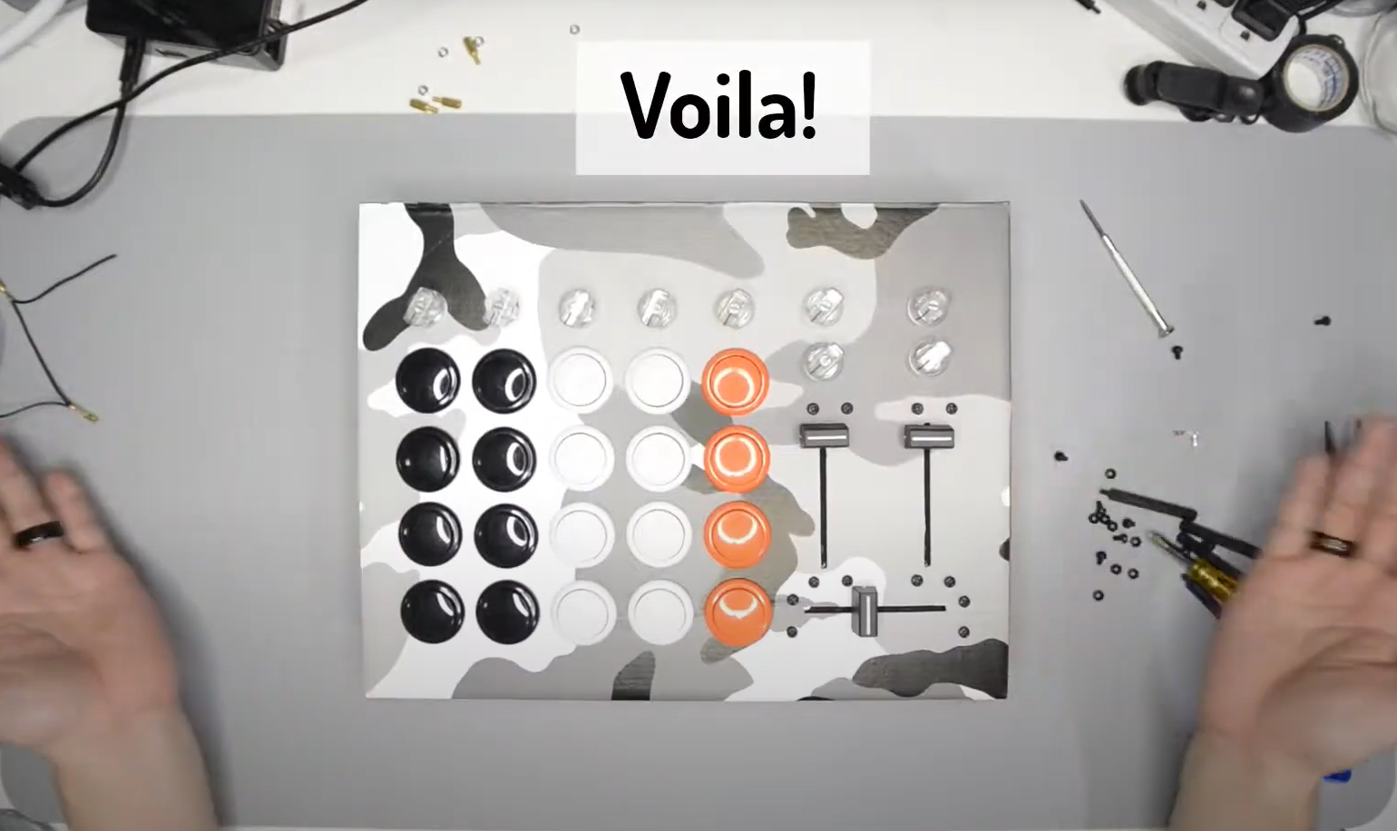
Voila!
Assembly stage of the Mega Control is completed. It is now time to plug the controller into a computer and test it out!
Soldering – Strongly Recommend
If you’re new to soldering, don’t worry. It is fairly easy to solder, which involves the following process:
- Add a small amount of solder to the iron tip
- Place and hold the iron tip on the connection/joint you want to solder (in this case the button/switch pin and the wire)
- Touch the end of the solder reel onto the joint, but not the iron tip.
- When the joint is hot enough the solder will melt onto it.
- Lift the solder reel and iron off of the joint a give it a few seconds to dry
Please solder in a well-ventilated area and use safety glasses!
You are now ready to test the circuit. Open up your DAW/MIDI software of choice, connect to the MIDI device called ‘Teensy MIDI’ (or something similar), and start pressing the arcade buttons. Each button should send a different MIDI note or CC message, and when you flip the toggle switch they should start sending the opposite type of message. If some or none of the buttons are working go back over the circuit and make sure all the connections are correct, as well as checking that the wires are securely connected to the buttons.
Code
Library Source https://github.com/tttapa/Control-Surface
Built for Ardruino Mega 2560
/**
 * This is the code for UMS Mega Keys V1.
 *
 * @boards  Mega 2560
 *
 * Connections
 * -----------
 *
 * I used an Arduino Mega R3 with:
 * - 5 potentiometers on A0-A4
 * - 26 noteButtons
 * Modified by Panakronic
 * Written by PieterP
 * https://github.com/tttapa/Control-Surface
 */
 #include <Control_Surface.h>

USBMIDI_Interface usbmidi;

// If the jog wheels or other encoders are too slow in your software, increase
// this value.
// (It will be multiplied with the actual speed of the encoder, as the name
// implies.) Default is 1.
const int speedMultiplier = 1;


CCPotentiometer faders[] {
  { A0, {MIDI_CC::Channel_Volume, Channel_1}},
  { A1, {MIDI_CC::Channel_Volume, Channel_2}},
  { A2, {MIDI_CC::Channel_Volume, Channel_3}},
  { A3, {MIDI_CC::Channel_Volume, Channel_4}},
  { A4, {MIDI_CC::Channel_Volume, Channel_5}},

};

NoteButton switches[] {
  { 13, 0x10, 1,},
  { 12, 0x11, 1,},
  { 11, 0x12, 1,},
  { 10, 0x13, 1,},

  { 9,  0x14, 1,},
  { 8,  0x15, 1,},
  { 7,  0x16, 1,},
  { 6,  0x17, 1,},

  { 5,  0x18, 1,},
  { 4,  0x19, 1,},
  { 3,  0x1A, 1,},
  { 2,  0x1B, 1,},

  { 14, 0x1C, 1,},
  { 15, 0x1D, 1,},
  { 16, 0x1E, 1,},
  { 17, 0x1F, 1,},

  { 18,  0x20, 1,},
  { 19,  0x21, 1,},
  { 20,  0x22, 1,},
  { 21,  0x23, 1,},

  { 23,  0x24, 1,},
  { 25,  0x25, 1,},
  { 27,  0x26, 1,},
  { 29,  0x27, 1,},
  { 31,  0x28, 1,},
  { 33,  0x29, 1,},
};


void setup() {
  Control_Surface.begin();
  pinMode(LED_BUILTIN, OUTPUT);
}

void loop() { // Refresh all inputs
  Control_Surface.loop();

}
Wiring
Enclosure
Coming soon…