|
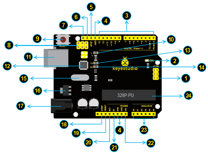
ICSP (In-Circuit Serial Programming) HeaderIn most case, ICSP is the AVR,an Arduino micro-program header consisting of MOSI, MISO, SCK, RESET, VCC, and GND. It is often called the SPI (serial peripheral interface) and can be considered an “extension” of the output. In fact, slave the output devices under the SPI bus host.
When connecting to PC, program the firmware to ATMEGA328P-PU. |
 |
Power LED IndicatorPowering the Arduino, LED on means that your circuit board is correctly powered on. If LED is off, connection is wrong. |
 |
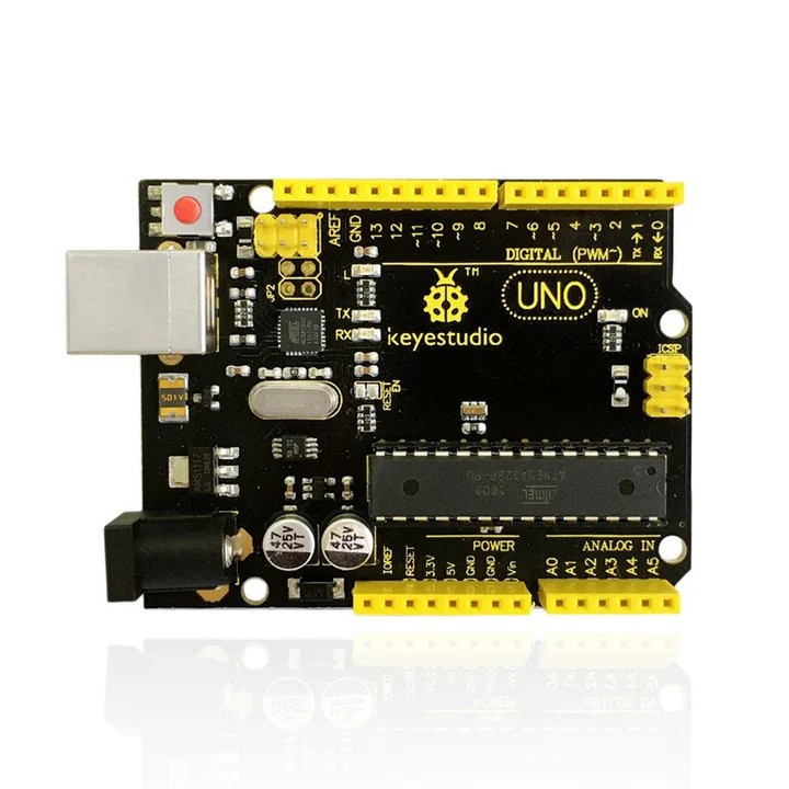
Digital I/OArduino UNO has 14 digital input/output pins (of which 6 can be used as PWM outputs). These pins can be configured as digital input pin to read the logic value (0 or 1). Or used as digital output pin to drive different modules like LED, relay, etc. The pin labeled “〜” can be used to generate PWM. |
 |
GND ( Ground pin headers)Used for circuit ground |
 |
AREFReference voltage (0-5V) for analog inputs. Used with analogReference(). |
 |
SDAIIC communication pin |
 |
SCLIIC communication pin |
 |
ICSP (In-Circuit Serial Programming) HeaderIn most case, ICSP is the AVR,an Arduino micro-program header consisting of MOSI, MISO, SCK, RESET, VCC, and GND. Connected to ATMEGA 16U2-MU. When connecting to PC, program the firmware to ATMEGA 16U2-MU. |
 |
RESET ButtonYou can reset your Arduino board, for example, start the program from the initial status. You can use the RESET button. |
 |
D13 LEDThere is a built-in LED driven by digital pin 13. When the pin is HIGH value, the LED is on, when the pin is LOW, it’s off. |
 |
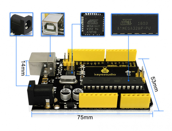
USB ConnectionArduino board can be powered via USB connector. All you needed to do is connecting the USB port to PC using a USB cable. |
 |
ATMEGA 16U2-MUUSB to serial chip, can convert the USB signal into serial port signal. |
 |
TX LEDOnboard you can find the label: TX (transmit) When Arduino board communicates via serial port, send the message, TX led flashes. |
 |
RX LEDOnboard you can find the label: RX(receive ) When Arduino board communicates via serial port, receive the message, RX led flashes. |
 |
Crystal OscillatorHelping Arduino deal with time problems. How does Arduino calculate time? by using a crystal oscillator.
The number printed on the top of the Arduino crystal is 16.000H9H. It tells us that the frequency is 16,000,000 Hertz or 16MHz. |
 |
Voltage RegulatorTo control the voltage provided to the Arduino board, as well as to stabilize the DC voltage used by the processor and other components.
Convert an external input DC7-12V voltage into DC 5V, then switch DC 5V to the processor and other components. |
 |
DC Power JackArduino board can be supplied with an external power DC7-12V from the DC power jack. |
 |
IOREFUsed to configure the operating voltage of microcontrollers. Use it less. |
 |
RESET HeaderConnect an external button to reset the board. The function is the same as reset button (labeled 9) |
 |
Power Pin 3V3A 3.3 volt supply generated by the on-board regulator. Maximum current draw is 50 mA. |
 |
Power Pin 5VProvides 5V output voltage |
 |
VinYou can supply an external power input DC7-12V through this pin to Arduino board. |
 |
Analog PinsArduino UNO board has 6 analog inputs, labeled A0 through A5.
These pins can read the signal from analog sensors (such as humidity sensor or temperature sensor), and convert it into the digital value that can read by microcontrollers) Can also used as digital pins, A0=D14, A1=D15, A2=D16, A3=D17, A4=D18, A5=D19. |
 |
MicrocontrollerEach Arduino board has its own microcontroller. You can regard it as the brain of your board.
The main IC (integrated circuit) on the Arduino is slightly different from the panel pair. Microcontrollers are usually from ATMEL. Before you load a new program on the Arduino IDE, you must know what IC is on your board. This information can be checked at the top of IC. |